Donate for the Poorest Students

You can support for the poorest students. Copy the link in your browser & Donate as small as possible.. https://www.paypal.com/donate/?hosted_button_id=R3MNE48JU7KGL
Showing posts with label Big construction Design. Show all posts

Sunday, 16 July 2023

Soil Compaction Control Cal:Engineering & Science Calculators: Free Online Tools

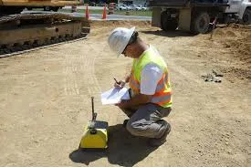
Definition:Soil compaction is the process of mechanically increasing the density of soil by reducing the air voids between soil particles.
/* */ Soil Compaction Control Calculator

Soil Compaction Control Calculator

Continue Definition:
Soil compaction is the process of mechanically increasing the density of soil by reducing the air voids between soil particles. It is a crucial aspect of construction, particularly in earthworks, road construction, and foundation preparation. Proper compaction ensures stability, reduces settlement, and improves the load-bearing capacity of the soil.
Factors Involved in Soil Compaction Control Calculation
Dry Density (ρd): It is the mass of solid soil particles per unit volume of soil. It is expressed in kg/m³ or lb/ft³.
Maximum Dry Density (MDD): It is the highest dry density that can be achieved for a given soil through compaction. It is determined in the laboratory using standard Proctor or modified Proctor tests. It is expressed in kg/m³ or lb/ft³.
Compaction Percentage (CP): It is the ratio of the in-situ dry density to the maximum dry density, expressed as a percentage. It indicates the degree of compaction achieved in the field.
Formula: CP = (ρd / MDD) * 100
Soil Depth: It is the thickness of the soil layer being compacted. It is expressed in centimeters (cm) or inches.
Sample Values
MDD: 1800 kg/m³ (typical value for well-graded sandy soil)
ρd: 1700 kg/m³
Soil Depth: 15 cm
Examples
Example 1:
A soil has a maximum dry density (MDD) of 1900 kg/m³. After compaction in the field, the dry density (ρd) is found to be 1800 kg/m³. Calculate the compaction percentage (CP).
Solution:
CP = (ρd / MDD) * 100 = (1800 / 1900) * 100 = 94.74%
Example 2:
A soil is required to be compacted to 95% of its maximum dry density (MDD). The MDD of the soil is 2000 kg/m³. Calculate the required dry density (ρd) in the field.
Solution:
CP = (ρd / MDD) * 100
95 = (ρd / 2000) * 100
ρd = (95 * 2000) / 100 = 1900 kg/m³
Additional Suggestions
Optimum Moisture Content (OMC): It is the moisture content at which the maximum dry density is achieved. It is determined in the laboratory along with the MDD. Maintaining the OMC during compaction is crucial for achieving the desired compaction.
Compaction Equipment: The type of compaction equipment used depends on the soil type, soil depth, and project requirements. Different types of compactors include smooth-wheeled rollers, vibratory rollers, sheepsfoot rollers, and rammers.
Field Density Tests: Several methods are available for determining the in-situ dry density in the field, including the sand cone method, the rubber balloon method, and nuclear density gauges.
Layer Compaction: For deep soil layers, compaction is done in layers to ensure uniform compaction throughout the depth. Conclusion
Soil compaction control calculation is essential for ensuring the quality and performance of construction projects. By understanding the factors involved and performing the necessary calculations, engineers can achieve the desired compaction and ensure the stability and durability of soil structures.
Ways to Earn Money Using Soil Compaction Calculation
1. **Geotechnical Consulting:**
* Offer soil testing and analysis services to construction companies, developers, and government agencies.
* Perform laboratory tests to determine MDD and OMC.
* Conduct field density tests to ensure compliance with specifications.
* Provide recommendations on compaction methods and equipment.
2. **Construction Quality Control:**
* Work as a quality control inspector on construction sites.
* Monitor compaction operations and perform field density tests.
* Ensure that the required compaction is achieved.
* Prepare reports and documentation for quality assurance.
3. **Earthwork Contractors:**
* Specialize in earthwork and site preparation for construction projects.
* Use soil compaction calculations to optimize compaction operations.
* Ensure stability and prevent settlement of soil structures.
4. **Pavement Design and Construction:**
* Work with pavement engineers and contractors on road and highway projects.
* Perform soil compaction calculations for subgrade and base layers.
* Ensure the long-term performance and durability of pavements.
5. **Foundation Design and Construction:**
* Collaborate with structural engineers and foundation contractors.
* Perform soil compaction calculations for foundation support.
* Ensure the stability and prevent settlement of structures.
6. **Agricultural Applications:**
* Advise farmers on soil management practices to prevent soil compaction.
* Promote sustainable agriculture and improve crop yields.
7. **Environmental Consulting:**
* Assess the impact of soil compaction on water infiltration and runoff.
* Develop solutions for erosion control and stormwater management.
**Real-Life Applications**
1. **Building Construction:** Soil compaction is essential for foundation stability and preventing settlement.
2. **Road and Highway Construction:** Proper compaction ensures the long-term performance and durability of pavements.
3. **Dam Construction:** Soil compaction is crucial for the stability and safety of earth dams.
4. **Airport Construction:** Compaction is essential for runway and taxiway construction to withstand heavy aircraft loads.
5. **Landfill Construction:** Soil compaction is used to create stable and impermeable liners for waste containment.
6. **Sports Field Construction:** Compaction is important for creating level and stable playing surfaces.
7. **Agricultural Land Management:** Controlled compaction can improve soil health and crop yields.
By applying soil compaction calculations in these real-life applications, professionals can ensure the quality, safety, and sustainability of various projects and earn money through their expertise.
Click This link for your soil testing Calculation

Settlement Analysis of Piled Foundation Calculator:Engineering & Science Calculators: Free Online Tools

Definition: Settlement analysis Calculation of a piled foundation is the process of estimating how much a foundation will settle under a specified load.The formula provided, settlement = (load * pileLength) / (pileModulus + soilModulus), is a highly simplified representation of pile settlement.
Settlement Analysis of Piled Foundation Calculator

Settlement Analysis of Piled Foundation Calculator

Continue Definition: The formula provided, settlement = (load * pileLength) / (pileModulus + soilModulus), is a highly simplified representation of pile settlement. It doesn't account for many crucial factors and is only suitable for very preliminary estimations. A more accurate analysis requires considering several additional parameters and using more complex methods.
Let's break down the simplified approach first and then discuss the necessary complexities.
Factors Involved (Simplified):
Applied Load (Q): The total vertical load applied to the pile (kN).
Pile Modulus (Ep): The modulus of elasticity of the pile material (kN/m²). This represents the stiffness of the pile.
Pile Length (L): The embedded length of the pile in the soil (m).
Soil Modulus (Es): A representative modulus of the soil surrounding the pile (kN/m²). This is a significant simplification, as soil stiffness varies with depth and stress level.
Output Equation (Simplified):
Settlement (S) = (Q * L) / (Ep + Es)
Sample Values (Simplified):
Applied Load (Q): 1000 kN
Pile Modulus (Ep): 25 x 10⁶ kN/m² (Typical for concrete)
Pile Length (L): 10 m
Soil Modulus (Es): 10 x 10³ kN/m² (A very rough estimate; soil modulus varies greatly)
Examples (Simplified):
Example 1:
A concrete pile (Ep = 25 x 10⁶ kN/m²) is 12 m long and subjected to a load of 800 kN. The estimated soil modulus is 8 x 10³ kN/m². Calculate the settlement using the simplified formula.
Settlement (S) = (800 kN * 12 m) / (25 x 10⁶ kN/m² + 8 x 10³ kN/m²) ≈ 3.84 x 10⁻⁴ m or 0.384 mm
Example 2:
A steel pile (Ep = 200 x 10⁶ kN/m²) is 15 m long and carries a load of 1500 kN. The estimated soil modulus is 12 x 10³ kN/m². Calculate the settlement.
Settlement (S) = (1500 kN * 15 m) / (200 x 10⁶ kN/m² + 12 x 10³ kN/m²) ≈ 1.12 x 10⁻⁴ m or 0.112 mm
Critical Limitations and Necessary Considerations for Realistic Settlement Analysis:
The simplified method has significant limitations:
Soil Heterogeneity: Soil properties vary with depth. A single "soil modulus" is a gross oversimplification. Layered soil profiles must be considered.
Pile-Soil Interaction: The formula doesn't accurately model the complex interaction between the pile and the surrounding soil. Skin friction along the pile shaft and end bearing at the pile tip are crucial.
Non-Linear Soil Behavior: Soil behavior is non-linear, meaning its stiffness changes with stress. The simplified formula assumes linear elasticity.
Group Effects: If piles are used in groups (which is very common), the settlement of one pile influences the settlement of adjacent piles. This "group effect" is not accounted for.
 
Time-Dependent Settlement: Some soils (especially clays) exhibit time-dependent settlement (consolidation), which the simplified formula doesn't capture.
Pile Type and Installation Method: The method of pile installation (driven, bored, etc.) significantly affects pile behavior.  
More Accurate Methods for Settlement Analysis:
Elastic Solutions: These methods use elastic theory to model pile-soil interaction, considering skin friction and end bearing. They are more accurate than the simplified formula but still have limitations.
Load Transfer Methods: These methods divide the pile into segments and analyze the load transfer between the pile and the soil at each segment.
 
Numerical Methods (Finite Element Analysis): These are the most advanced methods, capable of modeling complex soil behavior, pile-soil interaction, and group effects.
Suggestions:
Do not rely on the simplified formula for design purposes. It's only for very rough estimations.
Consult a Geotechnical Engineer: Accurate pile settlement analysis requires expertise in soil mechanics and foundation engineering.
Use appropriate software: Several geotechnical software packages are available for pile settlement analysis.  
In summary, while the provided formula gives a basic idea, it's crucial to understand its limitations. Real-world pile settlement analysis requires more sophisticated methods and should be performed by qualified geotechnical engineers.

How is it possible to Earn Money using the Calculation???

You're interested in how expertise in pile settlement analysis can be turned into income. Here are several ways to earn money by applying these calculations in real-life applications:
1. Geotechnical Engineering and Consulting:
Pile Foundation Design: This is the core application. Geotechnical engineers are hired to design pile foundations for various structures, including:
High-rise buildings
Bridges and overpasses
Industrial plants and factories
Offshore platforms and wind turbines
Tanks and storage facilities
Settlement Analysis and Reports: Providing detailed settlement analyses, including calculations for immediate, consolidation, and secondary settlement, is a crucial service
.
These reports are essential for:
Ensuring the stability and serviceability of structures
Obtaining building permits and regulatory approvals
Resolving disputes related to foundation performance
Geotechnical Investigations: Conducting site investigations (soil borings, laboratory testing) to determine the necessary soil properties (e.g., soil modulus, compressibility, shear strength) for accurate settlement analysis.
Pile Load Testing: Performing field tests to verify the load-bearing capacity and settlement behavior of piles. This provides valuable data for validating design assumptions and ensuring foundation performance.
2. Civil Engineering and Construction:
Foundation Design and Construction Management: Civil engineers specializing in foundation design use settlement analysis to ensure that foundations meet the required performance criteria. Construction managers use this knowledge to oversee pile installation and quality control.
Construction Quality Control/Quality Assurance (QC/QA): Monitoring pile installation, performing load tests, and verifying settlement predictions to ensure compliance with design specifications.
3. Specialized Consulting Services:
Forensic Geotechnical Engineering: Investigating foundation failures and providing expert opinions on the causes of excessive settlement.Expert Witness Testimony: Providing expert testimony in legal cases related to foundation problems and settlement disputes.
4. Software and Technology:
Software Development: Developing or contributing to geotechnical software that performs pile settlement analysis using various methods (elastic solutions, load transfer methods, finite element analysis).
Numerical Modeling and Analysis: Using advanced numerical methods (e.g., finite element analysis) to model complex pile-soil interaction and predict settlement behavior.

Real-Life Applications and How They Generate Income:

High-Rise Building Construction: Ensuring that the foundations of high-rise buildings can support the heavy loads and limit settlement to acceptable levels.
Bridge and Infrastructure Projects: Designing pile foundations for bridges, overpasses, and other infrastructure projects that can withstand heavy traffic loads and environmental conditions.
Industrial and Energy Projects: Designing pile foundations for industrial plants, power plants, and offshore platforms that can support heavy equipment and resist extreme loads.
Key Factors for Earning Potential:
Advanced Knowledge of Soil Mechanics and Foundation Engineering: A deep understanding of soil behavior, pile-soil interaction, and settlement analysis methods is essential.
Proficiency in Geotechnical Software: Familiarity with software like PLAXIS, FLAC, and other industry-standard tools is highly valuable.
Experience with Field Investigations and Testing: Practical experience in conducting geotechnical investigations and pile load tests is crucial.
Professional Licensing (P.E.): Obtaining a professional engineering license significantly enhances credibility and earning potential.
Strong Analytical and Problem-Solving Skills: The ability to analyze complex geotechnical problems and develop effective solutions is essential.
Effective Communication and Reporting Skills: The ability to communicate technical information clearly and concisely to clients, engineers, and other stakeholders is crucial.
By combining theoretical knowledge with practical experience and strong communication skills, professionals can leverage expertise in pile settlement analysis to build successful and rewarding careers in various fields related to civil engineering, geotechnical engineering, and construction

Reinforced Concrete Footing Calculator:Engineering & Science Calculators: Free Online Tools

Reinforced Concrete Footing Calculator

Reinforced Concrete Footing Calculator

Water Retaining Structure Calculator:Engineering & Science Calculators: Free Online Tools

Water Retaining Structure Calculator

Water Retaining Structure Calculator

Thursday, 13 July 2023

Geometric design in transportation engineering:Free Online Tool

Definition: Geometric design in transportation engineering refers to the process of designing the alignment and dimensions of roads, highways, and railways to ensure safe and efficient movement of vehicles. If the superelevation for a curve would be approximately 0.917%, meaning the outer edge of the curve would be elevated by that percentage compared to the inner edge.
Click the Translate button(see right) on this post to set your Own Language to understand more perfectly!!
Geometric Design Of Curvature Calculator

Geometric Design Of Curvature Calculator

Definition continue... Geometric design in transportation engineering refers to the process of designing the alignment and dimensions of roads, highways, and railways to ensure safe and efficient movement of vehicles. This design involves various factors, including radius, speed, and superelevation.
1. **Radius**: The radius of a curve in a road or railway refers to the curvature of that curve. It's measured from the center of the circle that best fits the curve. The radius affects the comfort and safety of vehicles traveling along the curve. A larger radius allows for higher speeds and smoother travel.
2. **Speed**: Speed is the rate at which an object moves along a path. In transportation engineering, speed limits are set based on factors like road conditions, traffic volume, and geometric design. Higher speeds typically require wider curves with larger radii to ensure safe travel.
3. **Superelevation**: Superelevation, also known as banking or cant, is the inward tilt of a road or railway curve provided to counteract the effect of centrifugal force on vehicles traveling along the curve. It helps reduce the tendency of vehicles to overturn or skid outward during turns. Superelevation is typically expressed as a percentage.
**Superelevation (e)** is calculated using the formula:
e = {{v^2}}/{{g .r}}
Where: \( e \) = Superelevation (in %) \( v \) = Design speed of the curve (in m/s or ft/s) \( g \) = Acceleration due to gravity (approximately 9.81 m/s² or 32.2 ft/s²) \( r \) = Radius of the curve (in meters or feet)
To calculate the required superelevation for a given curve, you would rearrange the formula as follows:
\
[ e = \frac{{v^2}}/{{g \cdot r}} \] Let's say the design speed (\( v \)) is 30 m/s and the radius (\( r \)) of the curve is 100 meters. Using the formula: \[ e = \frac{{(30 \, \text{m/s})^2}}{{9.81 \, \text{m/s}^2 \cdot 100 \, \text{m}}} \] \[ e = \frac{{900 \, \text{m}^2/\text{s}^2}}{{981 \, \text{m}^2/\text{s}^2}} \] \[ e ≈ 0.917 \]
So, the required superelevation for this curve would be approximately 0.917%, meaning the outer edge of the curve would be elevated by that percentage compared to the inner edge.
Geometric design, considering factors such as radius, speed, and superelevation, plays a crucial role in ensuring safe and efficient transportation infrastructure. Here are ten benefits of geometric design:
1. **Safety**: Proper geometric design helps reduce the likelihood of accidents by providing appropriate curvature (radius) for the given speed limit. Safer curves are achieved by balancing the design speed with the superelevation.
2. **Vehicle Stability**: Superelevation ensures that vehicles maintain stability while negotiating curves, reducing the risk of rollovers or skidding.
3. **Comfort**: Well-designed curves with appropriate radii and superelevation provide a smoother ride for passengers, reducing discomfort and fatigue during travel.
4. **Increased Speed**: By optimizing curves with larger radii and suitable superelevation, vehicles can safely travel at higher speeds, improving travel time and efficiency.
5. **Capacity**: Proper geometric design allows for increased traffic capacity by facilitating smoother flow of vehicles through curves, reducing congestion and improving overall traffic flow.
6. **Reduced Maintenance Costs**: Roads and railways with well-designed geometry experience less wear and tear on vehicles and infrastructure, leading to lower maintenance costs over time.
7. **Fuel Efficiency**: Efficient geometric design reduces the need for braking and acceleration, resulting in improved fuel efficiency for vehicles traveling along the route.
8. **Accessibility**: Geometric design considerations enable the creation of transportation infrastructure that is accessible to a wider range of users, including pedestrians, cyclists, and people with disabilities
.
9. **Environmental Impact**: By optimizing geometric design, transportation planners can minimize environmental impacts such as soil erosion and habitat fragmentation, contributing to sustainable development.
10. **Emergency Response**: Well-designed roads and railways facilitate faster and safer emergency response by providing smooth curves that allow emergency vehicles to maintain higher speeds while maneuvering through the infrastructure.
These benefits demonstrate the importance of considering geometric design factors such as radius, speed, and superelevation in transportation infrastructure planning and design, ultimately leading to safer, more efficient, and sustainable transportation systems.
How To Earn From The Traqnsportation Geometric Design Calculation
:
Here are ten ways to earn money by leveraging skills related to transportation geometric design calculations:
1. **Consulting Services**: Offer consulting services to transportation agencies, engineering firms, or construction companies for designing and optimizing roadways, highways, and railways based on geometric design principles.
2. **Training and Workshops**: Conduct training sessions and workshops on transportation geometric design calculations for engineers, urban planners, and transportation professionals.
3. **Software Development**: Develop software tools and applications that assist engineers and planners in performing geometric design calculations for transportation infrastructure projects.
4. **Freelance Work**: Freelance as a transportation engineer specializing in geometric design calculations, offering your expertise on platforms like Upwork or Freelancer to clients worldwide.
5. **Educational Content Creation**: Create educational content such as online courses, ebooks, or video tutorials covering topics related to transportation geometric design calculations, and sell them through platforms like Udemy or Teachable.
6. **Research and Development**: Engage in research and development activities to improve existing geometric design calculation methods or develop new techniques, which can be licensed or sold to engineering firms or government agencies.
7. **Project Management**: Provide project management services for transportation infrastructure projects, overseeing the implementation of geometric design solutions and ensuring compliance with regulations and standards.
8. **Expert Witness Services**: Offer expert witness services in legal cases related to transportation accidents or disputes involving geometric design issues, providing expert testimony based on your expertise.
9. **Customized Solutions**: Develop customized geometric design solutions tailored to specific client needs or unique project requirements, offering a competitive advantage in the marketplace.
10. **Partnerships and Collaborations**: Partner with engineering firms, software developers, or government agencies to collaborate on transportation infrastructure projects or joint ventures, leveraging complementary expertise and resources.
By leveraging your expertise in transportation geometric design calculations, you can explore various opportunities to earn money and build a successful career in this specialized field.
Do YOU Want To Earn Money In Various Ways, Click The Link & Explore Your Field of Interest!!!

Dam Stability Calculator:Engineering & Science Calculators: Free Online Tools

Dam Stability Calculator

Dam Stability Calculator

Trench Shoring Calculator:Engineering & Science Calculators: Free Online Tools

Trench Shoring Calculator

Trench Shoring Calculator

Bridge Design Calculator:Calculators for Students, Engineers & Researchers:free Online Tool

Definition: Bridge design is a highly complex engineering discipline requiring specialized knowledge, software, and adherence to specific codes and standards. The following is a simplified overview and does not constitute professional engineering advice.
Click the Translate button(see right) on this post to set your Own Language to understand more perfectly!!
Bridge Design Calculator

Bridge Design Calculator

Definition Continue: A Complex Challenge: Bridge Design Calculations
Disclaimer: Bridge design is a highly complex engineering discipline requiring specialized knowledge, software, and adherence to specific codes and standards. The following is a simplified overview and does not constitute professional engineering advice.
The Complexity of Bridge Design
Unlike simple structures, bridges involve multiple components, loads, and environmental factors. While length, width, and height are essential parameters, they alone cannot determine the bridge's structural integrity.
Key Factors in Bridge Design:
Loads: Dead load (bridge weight), live load (vehicles, pedestrians), wind load, seismic load, and environmental loads (snow, ice, etc.)
Materials: Concrete, steel, or timber, each with different properties and design considerations.
Geometry: Bridge type (beam, truss, arch, suspension), span length, and cross-sectional dimensions.
Soil Conditions: Soil bearing capacity, groundwater levels, and seismic activity.
Hydrology: Water flow, flood levels, and scour potential.
Codes and Standards: Adherence to design codes and standards for safety and performance.
Simplified Approach: Understanding the Challenge
While it's impossible to provide a single equation for bridge design, we can illustrate the complexity with a basic example:
Beam Deflection: A simplified equation for the deflection of a simply supported beam under a uniformly distributed load (like a bridge deck) is:
δ = (5 * w * L^4) / (384 * E * I)
Where:
δ = deflection
w = distributed load
L = span length
E = modulus of elasticity of the material
I = moment of inertia of the beam's cross-section
This equation only considers a basic scenario and doesn't account for other loads, material properties, or structural complexities.
The Importance of Specialized Software
Modern bridge design heavily relies on specialized software that can analyze complex structural systems, considering various load combinations and material properties.
Conclusion
Bridge design is a multidisciplinary field requiring expertise in structural engineering, materials science, hydrology, and geotechnical engineering. While length, width, and height are essential parameters, they are just a starting point. A comprehensive bridge design involves a systematic approach considering numerous factors and utilizing advanced engineering tools.

Load Calculations in Bridge Design

Understanding Loads
Loads are the forces acting on a bridge. They can be classified as:  
Dead loads: The weight of the bridge itself, including structural elements, wearing surfaces, and utilities.  
Live loads: Loads from moving vehicles, pedestrians, and other dynamic forces.  
Environmental loads: Wind, snow, ice, earthquakes, and temperature variations.
Load Calculations:
To determine the design loads for a bridge, engineers consider various load combinations based on probability and severity.
 
Example: A simply supported beam bridge carrying vehicular traffic
Dead load:
Weight of the beam, deck, and other structural elements.
Calculated based on material density and dimensions.
Live load:
Vehicle loads (trucks, cars, pedestrians)
Determined by design codes (e.g., AASHTO, Eurocode)
Load distribution patterns (concentrated, uniform)
Impact load:
Dynamic effects of moving vehicles
Considered as a percentage of live load
Other loads:
Wind, snow, temperature effects
Determined based on local climate and design codes
Load Combinations:
Different load combinations are considered to determine the maximum design loads.
Load factors are applied to each load type to account for uncertainties.
Example Calculation:
Determine dead load: Calculate the weight of the beam, deck, and other components based on their dimensions and material densities.
Determine live load: Select appropriate design vehicle loads based on the bridge's location and traffic volume.
Calculate impact load: Apply an impact factor to the live load.

Combine loads: Determine critical load combinations based on design codes (e.g., maximum live load + dead load, maximum live load + dead load + wind load).

Note: This is a simplified example. Actual bridge design involves complex load calculations, considering multiple load cases and load combinations to ensure the bridge's safety and serviceability.
Beam Deflection Calculation Example
Understanding the Variables:
Before we calculate deflection, let's define the variables in the equation:
δ (deflection): The maximum vertical displacement of the beam from its original position.
w (distributed load): The load acting on the beam per unit length.
L (span length): The distance between the two supports of the beam.
E (modulus of elasticity): A material property representing its stiffness.
I (moment of inertia): A geometric property of the beam's cross-sectional shape, indicating its resistance to bending.
Sample Values:
Let's consider a simply supported steel beam with the following properties:
Length (L): 5 meters
Distributed load (w): 10 kN/m (10,000 N/m)
Modulus of elasticity (E): 200 GPa (200 x 10^9 N/m²)
Moment of inertia (I): 1.5 x 10^-5 m^4 (assuming a standard I-beam section)
Calculation:
Using the formula:
δ = (5 * w * L^4) / (384 * E * I)
Substitute the values:
δ = (5 * 10000 N/m * (5 m)^4) / (384 * 200 x 10^9 N/m² * 1.5 x 10^-5 m^4)
Calculate the deflection:
δ ≈ 0.0104 m or 10.4 mm
Precautions and Considerations:
Deflection Limits: The calculated deflection should be compared to allowable deflection limits specified in design codes to ensure serviceability.
Load Combinations: Consider other loads (live, wind, etc.) and their combinations for a more accurate analysis.
Material Properties: Ensure accurate values for modulus of elasticity and other material properties.
Boundary Conditions: The assumed simple supports might not represent actual conditions. Other support conditions (fixed, cantilever) require different deflection formulas.  
Shear Effects: For long and slender beams, shear deformations might become significant.
Dynamic Loads: Consider dynamic effects for moving loads (e.g., vehicles).
By following these guidelines and using more advanced analysis methods, engineers can design safe and efficient beam structures.

How To Earn From The Bridge Design Calculation in our real life application????

:
Monetizing Bridge Design Calculation Knowledge
Understanding bridge design calculations is essential for engineers and professionals involved in infrastructure development. Here's how this knowledge can be monetized:
Consulting Services
Bridge Design: Offer expertise in designing bridges, from conceptualization to detailed engineering plans.
Structural Analysis: Conduct structural analysis for existing bridges to assess their condition and recommend rehabilitation or replacement.
Load Analysis: Evaluate load combinations and their impact on bridge structures.
Material Selection: Advise on the selection of appropriate materials for bridge construction.
Software Development
Bridge Design Software: Develop software tools for bridge engineers to automate calculations and design processes.
Structural Analysis Software: Create software for analyzing bridge structures under various load conditions.
Education and Training
Workshops and Seminars: Conduct training programs on bridge design, analysis, and construction.
Online Courses: Develop online courses on bridge engineering principles and software applications.
Government and Public Sector
Infrastructure Planning: Work with government agencies in developing bridge construction plans and standards.
Bridge Inspection: Conduct inspections of existing bridges to assess their condition and recommend maintenance or repair.
Research and Development
New Bridge Design Concepts: Research and develop innovative bridge designs for improved performance and sustainability.
Material Research: Explore new materials and technologies for bridge construction.
Key to Success:
Deep understanding of structural engineering principles and bridge design standards.
Proficiency in using bridge design software and calculation tools.
Strong communication and interpersonal skills to collaborate with clients and teams.
Networking with engineers, contractors, and government officials.
By effectively applying your knowledge of bridge design calculations, you can create value for the infrastructure industry and generate income through various avenues.
Do YOU Want To Earn Money In Various Ways, Click The Link & Explore Your Field of Interest!!!

Geotechnical Parameters Calculator:Calculators for Students, Engineers & Researchers:free Online Tool:

Geotechnical Parameters Calculator

Geotechnical Parameters Calculator

Deep Excavation Calculator:Calculators for Students, Engineers & Researchers:free Online Tool:

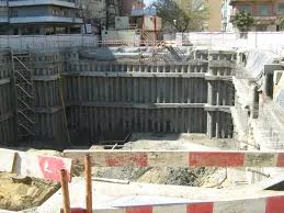
Definition:A deep excavation is an excavation that extends significantly below the original ground surface. The design and execution of such excavations require careful consideration of various factors to ensure safety and stability.
Click the Translate button(see right) on this post to set your Own Language to understand more perfectly!!
Deep Excavation Calculator

Deep Excavation Calculator

Excavation Details

Support System Details

DefinitionContinue: Deep Excavation

A deep excavation is an excavation that extends significantly below the original ground surface. The design and execution of such excavations require careful consideration of various factors to ensure safety and stability.
Key Parameters:
Excavation Depth (m): The vertical distance between the original ground surface and the bottom of the excavation.
Excavation Width (m): The horizontal distance across the excavation.
Support System Type: The type of structure used to retain the excavated soil and prevent collapse. Common types include sheet piles, secant piles, and diaphragm walls.
Support System Thickness (m): The thickness of the support system elements.
Sample Values:
Excavation Depth: 15 meters
Excavation Width: 10 meters
Support System Type: Diaphragm wall
Support System Thickness: 0.6 meters
Example Calculation:
While there's no direct calculation for determining the optimal parameters for a deep excavation, these values can be used as a starting point for further analysis. The selection of excavation depth, width, and support system is influenced by factors such as:
Soil conditions: The type and strength of the soil will determine the required depth and support system.
Groundwater conditions: The presence of groundwater will impact the excavation stability and dewatering requirements.
Surrounding structures: The proximity of buildings and other structures will affect the excavation design.
Construction methods: The chosen excavation method (e.g., top-down, bottom-up) will influence the support system requirements.
Additional Considerations:
Soil investigation: A thorough geotechnical investigation is essential to understand soil properties and groundwater conditions.
Structural analysis: The support system must be designed to withstand the lateral earth pressures and other loads.
Monitoring: Instrumentation should be used to monitor ground movements and excavation stability during construction.
Safety measures: Appropriate safety measures must be implemented to protect workers and the public.
Note: Deep excavation design is a complex process requiring expertise in geotechnical engineering, structural engineering, and construction methods. The provided example is a simplified overview and should not be used for actual design without considering specific project conditions and applicable codes and standards.
Let's Delve Deeper: Support System Design for Deep Excavations
Understanding Support Systems
Support systems are crucial for the stability of deep excavations. Common types include:
Sheet Piles: Interlocking steel or concrete sheets driven into the ground.
Diaphragm Walls: Concrete walls constructed in-situ using a trenching process.  
Secant Piles: Overlapping concrete piles formed by excavating and filling with concrete in stages.
Soldier Piles and Lagging: Steel piles with horizontal timber or steel planks for temporary support.  
Design Considerations:
Soil Properties: Soil type, unit weight, cohesion, and angle of internal friction are essential for determining lateral earth pressures.
Groundwater Conditions: Water table level and permeability influence hydrostatic and hydrodynamic pressures.
Excavation Depth and Width: These dimensions determine the overall size of the support system.
Surrounding Structures: Proximity of buildings and other structures affects the allowable deformations and vibrations.
Construction Sequence: The order of excavation and installation of support elements impacts the design.
Calculation Example: Lateral Earth Pressure
A common method to estimate lateral earth pressure on a retaining wall is using Rankine's theory.
Active Earth Pressure:
Pa = Ka * γ * z^2
Where:
Pa = active earth pressure
Ka = active earth pressure coefficient
γ = soil unit weight
z = depth below ground surface
Passive Earth Pressure:
Pp = Kp * γ * z^2
Where:
Pp = passive earth pressure
Kp = passive earth pressure coefficient
Note: These are simplified equations, and actual design considers factors like soil cohesion, surcharge, and wall friction.
Support System Design
The support system must resist the lateral earth pressures and other loads. Structural analysis is required to determine the required thickness, spacing, and reinforcement of the support elements.
Additional Considerations:
Deflection and Movement: The support system should be designed to accommodate expected movements and deformations.
Waterproofing: If groundwater is present, waterproofing measures may be necessary to prevent water ingress.
Construction Sequencing: The installation of the support system should be coordinated with the excavation process.
Monitoring: Instrumentation is essential to monitor the behavior of the excavation and support system during construction.  
By carefully considering these factors and utilizing appropriate design methods, engineers can ensure the safety and stability of deep excavations.

How To Earn From The Deep Excavation Calculation in our real life application????

:
Monetizing Deep Excavation Knowledge
Understanding deep excavation principles is crucial in various industries. Here's how this knowledge can be monetized:
Consulting Services
Geotechnical Engineering: Offer expertise in soil investigation, ground water analysis, and slope stability assessment for deep excavations.
Excavation Design: Design and optimize deep excavation projects, considering factors like support systems, dewatering, and ground improvement.
Construction Supervision: Oversee deep excavation projects to ensure compliance with design and safety standards.
Risk Assessment: Evaluate potential hazards and develop mitigation plans for deep excavations.
Software Development
Excavation Simulation Software: Develop software to simulate excavation processes and predict ground behavior.
Support System Design Software: Create software for designing and optimizing support systems.
Education and Training
Workshops and Seminars: Conduct training programs on deep excavation techniques, safety, and regulations.
Online Courses: Develop online courses on geotechnical engineering and excavation methods.
Other Avenues
Expert Witness: Provide expert testimony in legal cases involving excavation-related disputes.
Research and Development: Contribute to research on new excavation technologies and methods.
Key to Success:
Deep understanding of geotechnical engineering principles and excavation methods.
Proficiency in using geotechnical software and analysis tools.
Strong communication and interpersonal skills to collaborate with clients and teams.
Networking with engineers, contractors, and government officials.
By effectively applying your knowledge of deep excavation, you can create value for construction projects and generate income through various avenues.
Do YOU Want To Earn Money In Various Ways, Click The Link & Explore Your Field of Interest!!!

QR Code Generator:Engineering & Science Calculators: Free Online Tools.

Definition: A *QR code* (Quick Response code) is a two-dimensional barcode that stores data, like text, URLs, or other digital information, ...